- Mt8870 proteus library download how to#
- Mt8870 proteus library download serial#
- Mt8870 proteus library download software#
- Mt8870 proteus library download code#
- Mt8870 proteus library download download#
So, let’s get started with these New Proteus Libraries for Engineering Students. So, if you got into any trouble regarding these New Proteus Libraries then you can ask in comments and I will try my best to resolve your issues. These modules are all compatible with Arduino and PIC Microcontroller.
Mt8870 proteus library download download#
You can download them from their respective links and then can use them in your Proteus Projects.
Mt8870 proteus library download how to#
You should also have a look at How to add new Library in Proteus 8 Professional, if you are new to Proteus. So that engineering students can get benefit from these awesome libraries. I have shared many Proteus Libraries till now but they all are randomly spread in blog posts so today I thought to post all those Proteus Libraries links in this post. Today, I am going to share a list of New Proteus Libraries for Engineering Students. We have provided two demo codes working properly and easy to understand.Hello friends, I hope you all are fine and having fun with your lives. The programs given below will use above functions and display the complete string which is given by the programmer to display the data.


Mt8870 proteus library download code#
Important Post – Interfacing 7 Segment Display with 8051 Microcontroller Code RS=1 Register select should be high for writing data.R/W=0 Read/Write pin should be low for writing the data.RS=0 Register select should be low for sending commands.0x80 for positioning the cursor at first line.0X01 for clearing the display of the LCD.0xoC for making LCD display on and cursor off.0x38 is used for 8-bit data initialization.To initialize LCD to the 8051 the following instruction and commands are to be embed in to the functions RS and E are connected to PORT2 pins P2.0 and P2.1.Ī 10KΩ Potentiometer is used to adjust the contrast of the LCD.Ĭoming to the programming you should follow these steps: The data pins of the LCD are connected to PORT0 (first, the PORT0 pins must be pulled-HIGH with the help of a 1KΩ Resistor Pack).
Mt8870 proteus library download serial#
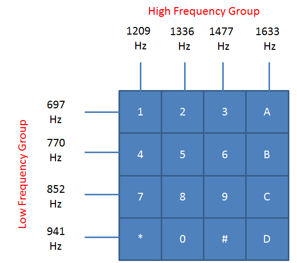
EA is pulled-HIGH with the help of a 10KΩ resistor. Sustituto del decodificador de tonos DTMF con un PIC12F675Características:El PIC12F675 se comunica vía serial con una interfaz que genera tonos DTMF y esta e. With the help of a 10μF Capacitor and a Push Button, you can reset the 8051 Microcontroller. RST Pin is pulled-LOW with the help of a 10KΩ Resistor. The crystal oscillator, along with two 33pF Capacitors, are connected to XTAL1 and XTAL2, which will provide the system clock to the microcontroller. To get the detailed information, Click Here and Download the Datasheet Interfacing 16×2 LCD with 8051 Circuit Diagram The list of commands given below:įor switching on LCD, blinking the cursor.įorce cursor to beginning of the first line As the DTMF decoder MT8870 is not present in the ICs given in the.
Mt8870 proteus library download software#
These commands are very important for displaying data in LCD. Proteus software has been used for the simulation of the circuit discussed above.


To send a command to the LCD just follows these steps:Ĭommands: There are some preset commands which will do a specific task in the LCD. To select the register select pin in write mode you have to make this pin high (RS=1), after selecting the register select you have to configure the R/W to write mode that is R/W should be low (R/W=0).įollow these simple steps for displaying a character or data For displaying a character you should enable the enable pin (pin 6) by giving a pulse of 450ns, after enabling the pin6 you should select the register select pin (pin4) in write mode. So by reading the above table you can get a brief idea how to display a character. A high to low pulse of about 450ns pulse is given to this pin.ĭB0-DB7 Data pins for giving data(normal data like numbers characters or command data) which is meant to be displayedīack light of the LCD which should be connected to Vccīack light of LCD which should be connected to ground. Reading and writing data to the LCD for reading the data R/W pin should be high (R/W=1) to write the data to LCD R/W pin should be low (R/W=0)Įnable pin is for starting or enabling the module. During the initializing sequence and other commands this pin should low. RS is the register select pin used to write display data to the LCD (characters), this pin has to be high when writing the data to the LCD. Used for adjusting the contrast commonly attached to the potentiometer. There are 16 pins in the LCD module, the pin configuration us given below This matrix differs for different 16×2 LCD modules, if you take JHD162A, this matrix goes to 5×8. Each character in the display is of size 5×7 pixel matrix.


 0 kommentar(er)
